this post was submitted on 30 Jan 2024
371 points (96.5% liked)
Open Source
31385 readers
193 users here now
All about open source! Feel free to ask questions, and share news, and interesting stuff!
Useful Links
- Open Source Initiative
- Free Software Foundation
- Electronic Frontier Foundation
- Software Freedom Conservancy
- It's FOSS
- Android FOSS Apps Megathread
Rules
- Posts must be relevant to the open source ideology
- No NSFW content
- No hate speech, bigotry, etc
Related Communities
- !libre_culture@lemmy.ml
- !libre_software@lemmy.ml
- !libre_hardware@lemmy.ml
- !linux@lemmy.ml
- !technology@lemmy.ml
Community icon from opensource.org, but we are not affiliated with them.
founded 5 years ago
MODERATORS
you are viewing a single comment's thread
view the rest of the comments
view the rest of the comments

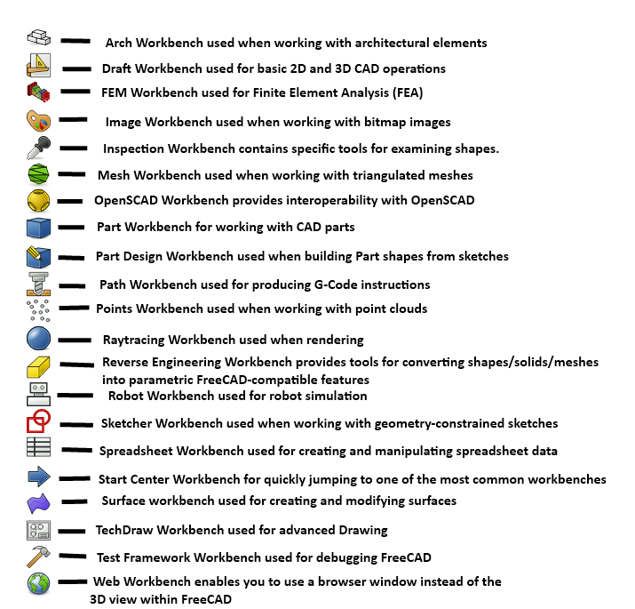
Yeah if you want to be reductive about it, FreeCAD is a GUI wrapper for OpenCASCADE, its CAD engine. FreeCAD is designed to be extensible; the workbench system allows for several different workflows, and using the Python API it's not that far out there to make your own workbench for specialized tasks. You could build a clockwork workbench if you were interested in designing escapements and such.
The tradeoff is it can seem overhwelming because there's a LOT of functionality in there. I do almost all of my work in the Spreadsheet, Sketcher and Part Design workbench, plus the A2Plus assembly workbench from the addon manager.
Curious to hear what it's like making parts with a spreadsheet. Is it like coding?
I use openscad a lot, and just tried using spreadsheets -- adding parameters to each property in a part still seems really clunky, compared to editing a scad file in Emacs, which I vastly prefer, especially now that there's AI code autocomplete.
I use the spreadsheet to hold dimensions/variable and formulas, makes it easier to modify designs. If I want to change a length, hole size height etc just change the spreadsheet values don't have to mess around with the sketches or 3d part designs directly.
One slightly frustrating thing i found is sometimes it fails to recompute the design or processes it incorrectly when values are changed by large amounts, that's probably more to do with how I design things though
I've seen it do things like that for two reasons:
If your change causes the number or arrangement of faces to change, this currently breaks things. This is what people in this thread talking about the topological naming issue are about; it keeps track of which faces are which by giving them names when they are created, and then when another feature is added to that face, it's linked by name. If you go back, edit an earlier step which creates more or fewer faces, it recomputes the model and might name them differently, so features suddenly move.
Sometimes I've had the sketcher just decide to turn a sketch inside out, because sometimes things like tangent constraints have two stable ways to be "fully constrained" or the existing constraints make different shapes with different dimension numbers.
I have seen both issues, when the sketcher starts to play up sometime I add more constraints to try to "anchor" a tangent in a certain direction but it can make the sketch messy The most reliable way I've found to stop it is small incremental changes e.g. say I want the length of a part to change my 40mm I'll change the size in 5mm increments allowing FC to recompute the model between each step. It's fiddly and frustrating but I can live with it, once you get to understand it's quirks Freecad can be very useful