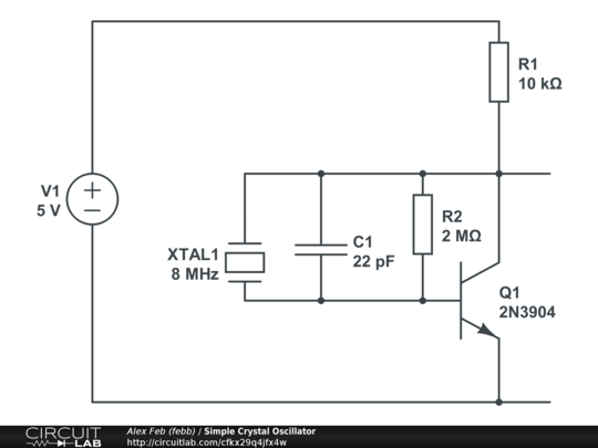
Preamble: I have been pushing the "I believe" button for way to long when it comes to crystal oscillators and their supporting components. The concept is simple, as they generally consist of proper loading and some kind of (pre)amplifier. "Small thing shake fast and you amplify". However, the full concept has never "clicked" in my brain and it feels like a huge knowledge gap that I should have filled years ago.
Asking these questions is horrendously embarrassing since I am a licensed ham and I should intuitively understand how all resonant circuits work by this point in my life. (Hopefully, y'all have a better way for me to visualize resonant circuits in general.)
From this schematic, all I see is a DC source, an amplifier, and maybe a super-simple RC tank circuit (of sorts) and the wave should never drop below 0v:

Some of the most basic crystal schematics (concept diagrams?) show a crystal connected directly to an AC source.
The concept of a crystal is simple: Apply a voltage and it moves, remove that voltage and it returns to its original shape. That kind of explains why kick-starting oscillation is needed, but that is not really where I am confused.
My questions are:
Is the crystal more closely related to an inductor in a basic RLC circuit? Is L being an approximate relationship to X a good way to visualize this?
Does the crystal "force" an RC resonant circuit to operate at a specific frequency because of its tendency to only operate efficiently at a given frequency in wildly different environments? (This question is a result of the first: Does an inductor act like a crystal in some ways?)
Since basic BJT amplifiers are generally shown with super-basic crystal schematics, is that amplification a functional part of generating a wave form? So, if the BJT was removed, the circuit would still function but it would be at a much lower current? (TBH, I am getting a gut feeling that the BJT is functionally related to an opamp with feedback in the above schematic, maybe?)
Thanks in advance for any education. Cheers!
(Oh, I do understand we are mixing AC and DC circuit concepts here, so that isn't an issue for me either. I also could just "look at the formulas" for building crystal circuits, but I need a better understanding of the core concepts first.)
Your general question about tank circuits / LC-oscillators might still stand. The main issue is that the XTAL is a completely separate and more precise than what pure electronics can deliver.
Do you know how to use LTSpice? Or any other simulator? You should setup a simple tank circuit and play with it.
There are two excitation here: At 0.1 milliseconds, I turn on the current to 0.5mA. And then at 0.2milliseconds, I turn the current off. This is the white line on that graph. Look what happens to the capacitor + inductor network. They "ring", passing energy between each other. (The green line is voltage, showing the energy bouncing between the circuit from that excitation)
When frequencies matter: we can tune a crystal + capacitor to 0.02% accuracy (20ppm) in a manufacturing setting (ie: without individually measuring a circuit. A mass production line of crystals+capacitors will all resonate at the same frequency +/- 0.02%). Meanwhile, your typical inductors/capacitors are +/-20% typically, and maybe +/- 10% if you're paying more.
And since quartz crystals are only a few cents, they end up being a very reliable and repeatable component to use. It is funny though: if you've got extremely sensitive equipment, you can measure the mechanical issues with crystals. (Ex: they'll change frequency ever so slightly based on how noisy a room is, or the heat/temperature, or even physical force like gravity / orientation can change its frequencies due to the mechanical nature of the vibrations). Its very very small in practice, but its fun to see if you got any absurdly accurate multimeter or frequency standards.
Some people think of oscillators as an amplifier circuit. Here's how.
The crystal is your filter. The NOT-gate (or the BJT) is the amplifier. When you amplify only one frequency, then naturally a sine-wave gets output at that frequency. That's all you're doing, really. You're taking a general energy excitation (which has energy in all kinds of frequencies), and then you shove that energy into a filter. The only energy that comes out of the filter is the frequency of the filter, and you set that as positive-feedback to your amplifier.
That amplifier adds more energy, which then returns the energy to the filter, and the process repeats as long as you have energy. The only difficult part is making sure the energy is returned within the correct phase-delay. (You don't want to be pushing when the crystal is pulling: you want to push when the crystal pushes, and you want to pull when the crystal pulls). The "NOT" gate is all you need to detect + amplify this concept.
That clicked. Thinking of a crystal as a filter is a good concept to start with, actually. I can also grasp thinking of it musically at the same time, so that is also a win.
Thanks again! I think you made the Internet just a little bit more of a nicer place. ;)